What are Jerks As electrical current moves through a wire it produces a magnetic field around the wire. Greater the current flow, stronger the magnetic field. When the heavy load is disconnected from the source the current flowing through the wire stops and the magnetic field around the wire collapses. The collapsing magnetic field induces a counter electromagnetic force in the wire causing the current to flow backwards back to the source. This returning current would appear as a electrical jerk or disturbance at the source. Of course this happens in an instant. ---OR--- When a transmission line suddenly becomes unavailable (trips due to fault) this can cause sudden frequency change in the system due to imbalance of supply to demand. Some types of plant are very sensitive to frequency and a change of more than a few hz in system frequency can cause significant plant damage. For this reason they are usually equipped with frequency protection and the plant will trip if the system frequency becomes too high or low. The 'jerk' referred to here could be the mechanical effect on the plant caused by the change in frequency. ---OR--- jerk is the rate of change of ramp rate. Because the plant jerk rate is limited for mechanical generation plant (the ramp rate is fixed, or almost fixed), a transmission system must have automatic load shedding: even if the plant could ramp up the power fast enough to handle the change, it cannot change the ramp rate fast enough to handle fault conditions.
To prevent automatic load shedding, power suppliers are required to meet minimum standards for Plant Jerk Rate Capability.
So a heavy jerk would be a sudden and sharp change in load. However, the word Jerk is not normally used except for power plant specifications.
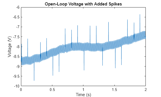
RESPONSE WITH JERKS:
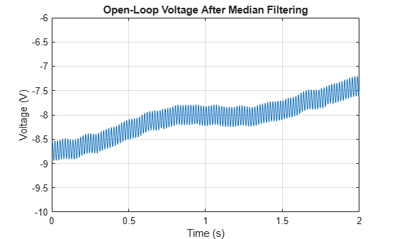
RESPONSE AFTER JERKS:
Some Market(industrial) research to minimize these Transients or Spikes are as follows:
For years, transients generated on the utility grid have plagued industrial and commercial facilities with a high concentration of variable-speed drives (VSDs) and other sensitive loads. The common sources of transients include transfer switch operation, lightning strikes, and utility-level capacitor switching. These transients cause sensitive equipment to trip on momentary overvoltages and result in substantial losses in productivity. The most common source of transients is utility switching of medium- and high-voltage capacitors for voltage regulation and power factor correction.
The traditional method of protecting VSD loads from utility-side transients involves installing line reactors in series with the VSD. The purpose of this practice is to increase line impedance and limit the transient at the drive terminals. In many cases, however, the end user installs the line reactors and discovers the problem has been lessened — but not eliminated.
Traditional surge protection devices (SPDs) employing metal-oxide varistors (MOVs) protect against high per-unit transients, such as those created by lightning, but they will not protect VSDs from capacitor-switching transients. For example, SPDs will typically limit transients to 1.8 per unit to 2.0 per unit, but small drives will trip at 1.3 to 1.4 per-unit overvoltages. Typical silicon-controlled rectifiers (SCRs) used in industrial environments may have only a 1.75 per-unit withstand capability (i.e.,1200V peak inverse voltage (PIV) rating) before they suffer permanent damage.
Recently, a new approach addressing the problem of capacitor-switching transients has been developed. The device, called the zero threshold surge suppressor (ZTSS), employs a passive diode bridge and electrolytic capacitors to shunt transient energy away from sensitive equipment. Unlike traditional SPDs, which technicians install in layers (e.g., main switchboard, subpanel, motor control center, sensitive load), only one ZTSS unit is required to protect an entire low-voltage substation service. The ZTSS is not MOV-based, so it will not degrade over time as multiple transients are suppressed. It can typically limit capacitor-switching transients to 1.2 per unit or less, effectively protecting VSD loads downstream of the device.
Because MOV characteristics are unsuitable for protecting small drives, a suppressor with a lower voltage characteristic is necessary. The ZTSS is designed to reduce the voltage spike below the overvoltage trip level of the adjustable-speed motor drives. It is a capacitor-based, phase-to-phase surge suppressor, and the suppressed spike amplitude is dependent on the time constant of the ZTSS's R/C circuit.
Design Fundamentals
The ZTSS consists of a 3-phase diode rectifier bridge and a DC capacitor bank (see Figure, on page 32). The circuit doesn't require a wye-connected secondary, and the diode bridge's peak output DC voltage is the peak line voltage of the supply. The capacitor bank consists of a number of resistors and capacitors that connect in parallel with each R/C leg protected by dual-element, time-delay fuses.
In practice, when the utility switches its power factor correction capacitors, the voltage on the line will fall first, followed by a sudden rise in voltage. This process repeats itself until the system settles down within one-half cycle.
The ZTSS absorbs the sudden change of the incoming high energy by charging and discharging the capacitors. The capacitors' rate of charge and discharge depends on the time constant of the R/C circuit.